

Top
Author
Updated
27 Apr 2022Form Number
TIPS0788PDF size
12 pages, 526 KBSubscribed to TIPS0788.
Thank you for your feedback.
Abstract
The 1x8 and 2x16 Local Console Managers (LCM8 and LCM16) are the next generation analog keyboard-video-mouse (KVM) console managers that provide enhanced local access, management, and security capabilities to Lenovo servers environments.
Change History
Changes in the April 27, 2022 update:
- Added a statement about the use of the Digital Activation Key in a tiered environment - Tiered consoles section
Introduction
The 1x8 and 2x16 Local Console Managers (LCM8 and LCM16) are the next generation analog keyboard-video-mouse (KVM) console managers that provide enhanced local access, management, and security capabilities to Lenovo server environments.
The LCM8 has eight target ports and supports one local user, and the LCM16 has 16 target ports and supports up to two local users. Local video resolution can be up to 1600x1200 or 1680x1050 (widescreen). Two level tiering allows you to manage up to 256 servers connected to multiple switches from one local console. The following figure shows the LCM8 and LCM16.
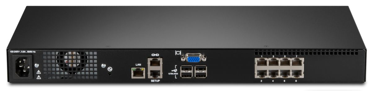
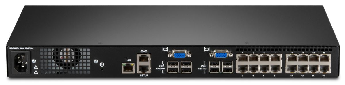
Figure 1. The Local Console Managers: LCM8 (top) and LCM16 (bottom)
Did you know?
The LCM8 and LCM16 support Two Factor Authentication (TFA), a system where two different security elements are used in conjunction to authenticate to a server or desktop. TFA is an authentication process where a person proves their identity with two methods: something you know (for example, a password or PIN) and something you have (such as a smart card). Use of TFA is growing due to requirements by governments and other institutions with a high need for security. An example of a TFA device that the Local Console Managers support is the CCID-compliant Common Access Card (CAC) reader.
You can use the LCM8 and LCM16 with a Global Console Manager to provide network-wide remote access with out-of-band access to servers, network equipment, and other devices with serial configuration or console ports all from a single appliance. This unified approach improves staff efficiency by reducing the time required to remotely diagnose, reconfigure, repair, or restore servers and network devices and other hardware with serial configuration, management consoles, or both.
Part number information
Ordering information is shown in Table 1. Note that when ordering with feature codes, use machine type-model 1754HC3 for the LCM8 and 1754HC4 for the LCM16.
Table 1. Ordering part numbers and feature codes
| Description | Part number | LCM8 feature code | LCM16 feature code |
| Local 1x8 Console Manager (LCM8) | 1754A1X | 1754HC3 fc 0725 | Not applicable |
| Local 2x16 Console Manager (LCM16) | 1754A2X | Not applicable | 1754HC4 fc 0726 |
| USB Conversion Option (UCO) (single) | 43V6147 | 1754HC3 fc 3757 | 1754HC4 fc 3757 |
| USB Conversion Option (UCO) 4-pack | 39M2895 | 1754HC3 fc 3756 | 1754HC4 fc 3756 |
| 1.5m KVM Conversion Option (KCO) 4-pack | 39M2897 | 1754HC3 fc 3754 | 1754HC4 fc 3754 |
| Virtual Media Conversion Option Gen2 (VCO2) | 46M5383 | 1754HC3 fc 5341 | 1754HC4 fc 5341 |
| 1754 LCM Digital Activation Key | 81Y2393 | 1754HC3 fc A17X | 1754HC4 fc A17X |
The LCM8 Local Console Manager includes the following items:
- An 8-port console switch
- Mounting hardware for an EIA space for rack sidewall compartment
- One 1U filler panel
- One 1.5 m C13/C14 rack power cable
- One RJ45-DB9F DCE adapter for use with the Setup port
- One RJ45-DB9M DTE adapter for use with the Modem port
- Eight terminators for daisy-chaining configurations
- Installation publications and warranty
The LCM16 Local Console Manager includes the following items:
- A 16-port console switch
- Mounting hardware for an EIA space for rack sidewall compartment
- One 1U filler panel
- One 1.5 m C13/C14 rack power cable
- One RJ45-DB9F DCE adapter for use with the Setup port
- One RJ45-DB9M DTE adapter for use with the Modem port
- 16 terminators for daisy-chaining configurations
- Installation publications and warranty
Each of the Conversion Option parts listed in Table 1 ships with:
- One Conversion Option (4-packs have four)
- Installation publications and warranty
The 1754 LCM Digital Activation Key includes the following:
- One USB key
- Installation instructions
The Local Console Managers enable you to share one workspace (keyboard, mouse, and display) across many target systems. The target systems are connected to the console switch via CAT-5 cables and the appropriate conversion option at the target end.
With server densities continually increasing, cable bulk remains a major concern for network administrators. The LCM8 and LCM16 switches significantly reduce KVM cable volume in the rack by utilizing the innovative conversion option cables and single, industry-standard CAT-5 UTP cabling. This allows a higher server density while providing greater airflow and cooling capacity. In addition, multiple target systems can be daisy-chained together using CAT-5 cables, and then all connected to the console switch using one cable, thereby eliminating a lot of cable clutter.
The 1754 LCM Digital Activation Key, part number 81Y2393, is a upgrade that turns the LCM KVM analog switch into a digital device enabling remote access to servers it is connected to. This device enables one remote user. The Digital Activation Key is a small USB device that is inserted into one of the USB ports at the rear of the unit. The following figure shows the Digital Activation Key. An LED on the end of the key shows its status.
Figure 2. 1754 LCM Digital Activation Key
Feature comparison
The following table compares the two LCM console switches.
| Feature | LCM8 | LCM16 |
|---|---|---|
| Part number | 1754A1X | 1754A2X |
| Number of local concurrent users | 1 | 2 |
| Local user connections: KVM | VGA + USB | VGA + USB |
| Local user connections: Extra USB | Yes | Yes |
| Remote user connections | Optional, with LCM Digital Activation Key |
Optional, with LCM Digital Activation Key |
| Maximum number of target systems: Direct (analog rack interface (ARI) ports) | 8 | 16 |
| Maximum number of target systems: Daisy-chained | 128 | 256 |
| Maximum number of target systems: Tiered configuration | 128 | 256 |
| Maximum video resolution | 1600x1200 (4:3) 1680x1050 (wide) |
1600x1200 (4:3) 1680x1050 (wide) |
| Support for USB Conversion Option, UCO (43V6147 and 39M2895) | Yes | Yes |
| Support for KVM (PS/2) Conversion Option, KCO (39M2897) | Yes | Yes |
| Support for Virtual Media Conversion Option Gen2, VCO2 (46M5383) | Yes | Yes |
| Support for Serial Conversion Option, (SCO) 46M5382 | No | No |
| Virtual Media | Yes | Yes |
| Chaining | Yes | Yes |
| Tiering | Yes | Yes |
| Two Factor Authentication (TFA) device support | Yes | Yes |
| Password protection | Yes | Yes |
| Serial port | Yes | Yes |
| True serial capabilities | No | No |
| Ethernet port (10/100) | Yes | Yes |
| Supports remote access with LCM Digital Activation Key | Yes | Yes |
| IPv6 support | Yes | Yes |
| Keep Alive feature in Conversion Options | Yes | Yes |
| Firmware upgrades to the console switch | Via Ethernet or serial | Via Ethernet or serial |
| Firmware upgrades to the COs | Via Web GUI or serial | Via Web GUI or serial |
| Input power | 100-240V, 50/60 Hz 8.5W power, 15W max |
100-240V, 50/60 Hz 8.5W power, 15W max |
Connections
The following figure shows the connections on the LCM16 Local Console Manager. The LCM8 Local Console Manager has identical connections except it only has one local user port and eight analog rack interface (ARI) ports, whereas the LCM16 has two local user ports and 16 ARI ports.
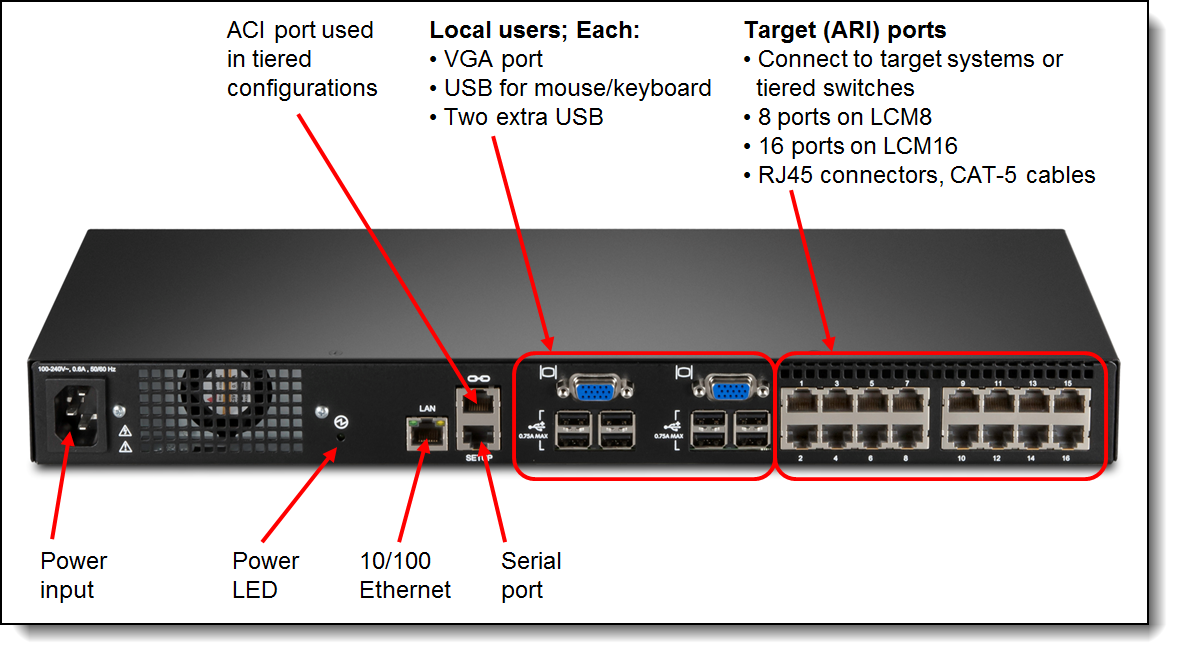
Figure 3. Connections on the LCM16 Local Console Manager
Note: The above figure shows the rear of the unit. There are no connectors on the front of the unit.
Features
Details about the features of the LCM8 and LCM16 are discussed in this section.
Local users
The LCM8 console switch enables one local user and the LCM16 console switch enables two local users to access any attached servers. Local displays are connected to the console switch using VGA analog connections and local keyboards and mice use USB connections.
Two additional USB ports (for a total of four USB ports) are available for each local user, and devices plugged into these ports (for example, memory key, optical drive, and CAC reader) are visible to the target servers if a Virtual Media Conversion Option Gen2 (VCO2), part number 46M5383 is used. Note, however, that the VCO2 does not support chaining of target systems. (There is more information about virtual media in the "Virtual media" section below.)
For the LCM16, if the target server is currently in use, a second user attempting to gain access will be given an opportunity to force a connection to the device if their preemption level is equal to or higher than the current user’s level. If the user attempting to gain access has a lower preemption level, the active user will be asked if they wish to give up control to the new user (a timeout is also configurable).
Target systems
The LCM16 has 16 target system ports (known as analog rack interface (ARI) ports) and the LCM8 has eight target system ports. These can be directly attached to systems with the appropriate USB or PS/2 conversion option connector on the end. These connections use standard CAT-5 cables. You can increase the number of connected target systems by two methods: chaining or a tiered arrangement of switches. (There is more information about these options in the Chaining and Tiered consoles sections below). Both methods mean that each of the eight or 16 ports will have multiple systems connected to it. You can mix connection methods.
Conversion options
These are cable-connector combinations that are connected between the CAT-5 cables from the console switches to the target systems. The figure below shows the conversion option cables that can be used with the console switches. The part numbers are listed in the Part number information section.
The KVM Conversion Option (KCO) is suitable for target servers with VGA and PS/2-style mouse and keyboard connections. The USB Conversion Option (UCO) is for systems with VGA and USB connections.
The Virtual Media Conversion Options (VCO and VCO2) supports the virtual media capability of the console switches; however, they do not support chaining.
Note: The KVM and USB conversion options are withdrawn from marketing.
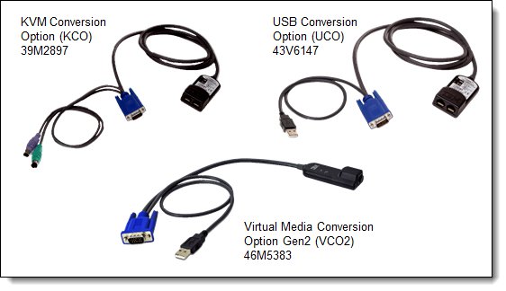
Figure 4. Supported conversion options
The built-in memory of each connection option helps simplify the configuration by assigning and retaining unique server identification codes for each attached server. This integrated intelligence enhances security and helps prevent unauthorized access to a server through cable manipulation. The connection option is powered directly from the server, providing Keep Alive functionality even if the server is not powered on.
Supported video resolutions are listed in the following table.
| VCO2 Standard (4x3) | VCO Widescreen (withdrawn) |
KCO & UCO (withdrawn) |
|---|---|---|
| 640 x 480 @ 60 Hz 800 x 600 @ 75 Hz 960 x 700 @ 75 Hz 1024 x 768 @ 75 Hz 1280 x 1024 @ 75 Hz 1600 x 1200 @ 60 Hz |
800 x 500 @ 60 Hz 1024 x 640 @ 60 Hz 1280 x 800 @ 60 Hz 1440 x 900 @ 60 Hz 1680 x 1050 @ 60 Hz 1920 x 1080 @ 60 Hz |
640 x 480 @ 60 Hz 800 x 600 @ 75Hz 1024 x 768 @ 75 Hz 1280 x 1024 @ 75 Hz |
Local and remote user interfaces
The LCM8 and LCM16 offer two user interfaces to manage connections:
- An on-screen display (OSCAR) accessible via the Print Screen button on either local user keyboard. This interface is used to control connectivity to the target servers.
- A Web browser interface accessible from any computer on the same Ethernet network as the console switch (provided the Ethernet port of the console switch is connected and properly configured). This interface is used to configure and manage the appliance.
Virtual media
The LCM8 and LCM16 support virtual media when the target systems are connected using the Virtual Media Conversion Option Gen2 (VCO2), part number 46M5383. You can use virtual media support to connect USB 2.0 media devices to the console switch using one of the four USB ports and make those devices available to any connected system. With this feature, you can install software, install, upgrade, or recover the operating system, update the BIOS code, or boot the target system from a USB drive.
Control of how the USB device is connected to the target system is managed through the user interface. The user interface presents the following configuration options:
- Virtual Media Locked: The locking option specifies whether a virtual media session is locked to the KVM session on the target device. When locking is enabled (default) and the KVM session is closed, the virtual media session will also be closed. When locking is disabled and the KVM session is closed, the virtual media session will remain active.
- Allow Reserved Sessions: Ensures that a virtual media connection can only be accessed with your user name and that no other user can create a KVM connection to that target device. When the associated KVM session is disconnected, the virtual media session may be disconnected according to the Locked setting.
- Write Access: With this option, you can specify whether the target system can write to the USB device (assuming it is writable).
- Encryption: You can configure encryption levels for virtual media sessions. The choices are None (default), 128-bit SSL (ARCFOUR), DES, 3DES, and AES.
Note that USB ports are assigned to a single virtual media session and cannot be independently mapped. This means you cannot map one USB device to one target system and another USB device to another target system.
Use of smart cards to authenticate access
The LCM8 and LCM16 switches allow you to use CCID-compliant smart cards to ensure access is authorized. Smart cards are pocket-sized cards that store and process information and enable Two Factor Authentication (TFA). Smart cards can be used to store identification and authentication to enable access to computers, networks, and secure rooms or buildings. Smart card readers are connected directly to the switch via one of the USB ports.
Note: For smart card use, the target device must be connected to the console switch using the Virtual Media Conversion Option Gen2 (VCO2), part number 46M5383. Other conversion options such as the VCO are not supported with smart cards.
Chaining
Withdrawn feature: Chaining requires the use of USB conversion options, however these are now withdrawn from marketing. Chaining is not supported with VCO2 conversion options.
Cable chaining enables users to manage a "daisy chain" of multiple servers through a single connection to the console switch, replacing many long cables with just a few short ones, simplifying rack management, helping lower cabling cost, and reducing setup, diagnostic, and maintenance times. The daisy-chain connectivity has the added advantage of thin, flexible, and industry-standard CAT5 cabling and standard RJ-45 connectors, eliminating the need for one-to-one, dedicated cable connections between KVM switch ports and managed devices. This cable chaining solution allows up to 16 target systems to be chained together and connected to one port on the switch.
The following figure shows an example of chaining three target systems from one port on the console switch. Each conversion option part number includes a CAT-5 cable to connect it to either the console switch or its neighboring conversion option. The console switch includes the terminator needed at the end of the daisy chain.
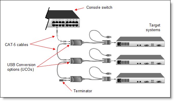
Figure 5. Chaining using USB Conversion Options
Note: Neither the Virtual Media Conversion Option (VCO) nor the Virtual Media Conversion Option 2 (VCO2) support chaining.
Tiered consoles
You can tier multiple rack console switches to enable access to additional servers. In a tiered system, an ARI port on the main rack console switch connects to the Analog Console Interface (ACI) port of a tiered rack console switch (see the Connections section for a photo showing the locations of these ports). Consider a tiered configuration if you want to manage servers connected to multiple switches from one central location. For example, you could have a primary LCM16 console switch with 16 switches tiered underneath it that all have servers chained to their ports.
The LCM8 and LCM16 support two levels of tiering. The use of virtual media and smart card authentication are both supported only when primary and secondary switches are LCM8 or LCM16 console switches.
The following figure shows an example of tiered consoles. The red connections are simply CAT-5 cables between an ARI port on the master and the ACI port of each secondary switch.
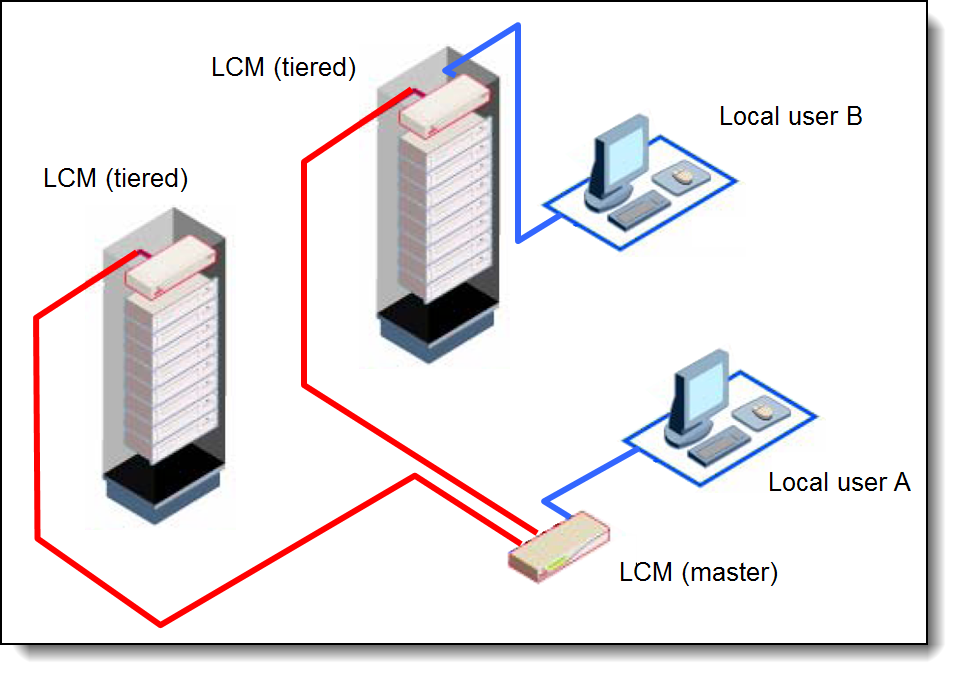
Figure 6. Tiered consoles
If there are local users attached to other tiered consoles, each can control target systems connected to that specific console. The local user at the primary console (Local user A in the figure) can preempt other local users if necessary.
The LCM8 supports up to 128 target systems and the LCM16 supports up to 256 target systems in a tiered configuration.
If the master switch is a Global Console Manager, GCM16 (1754D1X), or GCM32 (1754D2X), then tiering can also be used with the additional benefit of supporting remote network-attached users.
If you are using tiering and you have wish to enable remote access to the consoles using the Digital Activation Key, you only need the Digital Activation Key on the LCM that you are starting the session from. In a Primary > Secondary > Target cascade, a Digital Activation Key is needed on the Primary (master) console where you launch the session from, but it is not needed on the Secondary (tiered) consoles. You would only need to install the Digital Activation Key on the Secondary console if you plan to also initiate remote sessions from a Secondary console.
Physical specifications
The LCM8 and LCM16 have the following specifications:
Height: 4.37 cm (1.72 inches): 1 rack unit (1R)
Width: 43.2 cm (17 inches)
Depth: 16.5 cm (6.5 inches)
Weight: 1.9 kg (4.2 lb)
Operating environment
The adapter is supported in this environment:
- Temperature:
- Operating: 0° to 50°C (32° to 132°F)
- Non-operating: -20° to 70°C (-4° to 158°F)
- Relative humidity:
- 10% to 95%
Warranty
The LCM8 and LCM16 have a three-year limited warranty.
Related publications and links
For more information, refer to these documents and websites:
- Lenovo Press Product Guides for console switches and console kits:
https://lenovopress.com/servers/options/kvm - Local Console Manager LCM8 and LCM16 Installation and User's Guide
https://support.lenovo.com/docs/UM103303
Related product families
Product families related to this document are the following:
Trademarks
Lenovo and the Lenovo logo are trademarks or registered trademarks of Lenovo in the United States, other countries, or both. A current list of Lenovo trademarks is available on the Web at https://www.lenovo.com/us/en/legal/copytrade/.
The following terms are trademarks of Lenovo in the United States, other countries, or both:
Lenovo®
Other company, product, or service names may be trademarks or service marks of others.
Configure and Buy
Please select a locale
Full Change History
Changes in the April 27, 2022 update:
- Added a statement about the use of the Digital Activation Key in a tiered environment - Tiered consoles section
Changes in the June 2, 2019 update:
- Conversion options do not include a CAT-5 cable
Changes in the January 21, 2018 update:
- Update the tables of supported servers - Server support section
Changes in the July 12, 2017 update:
- Clarified that the 1754 LCM Digital Activation Key enables one remote user
Changes in the September 13, 2016 update:
- Updated Table 2 to indicate remote access is available with the optional LCM Digital Activation Key
Changes in the October 6, 2015 update:
- Updated the tables of supported servers
- Updated the Related publications section
First published: 6 August 2010


