

Top
Abstract
The BladeCenter HS21 XM has eight DIMM sockets letting clients install up to 64 GB of RAM. In addition, the HS21 XM offers two memory features that clients might want to implement: memory mirroring and memory sparing. This technote describes what these features are and what the configuration rules are to enable either of them.
Memory DIMM placement
The logical memory DIMM configuration is shown in Figure 2.
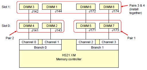
Figure 2. HS21 XM memory configuration
The standard HS21 XM models have two 512 MB DIMMs installed into sockets 5 and 7 as shown in Figure 2. The installation order is as follows:
The following table lists the blade server HS21 XM memory options. The number of ranks per DIMM is important when determining the space set aside for the hot spare memory in sparing mode.
The Ranks per DIMM are significant. You can mix DIMMs of different rank counts, subject to the configuration rules described below.
Figure 2. HS21 XM memory configuration
The standard HS21 XM models have two 512 MB DIMMs installed into sockets 5 and 7 as shown in Figure 2. The installation order is as follows:
- The first pair of DIMMs are installed in sockets 5 and 7.
- The second pair of DIMMs are installed in sockets 4 and 2.
- The third and fourth pair are installed together at the same time in sockets 1, 3, 6, and 8.
The following table lists the blade server HS21 XM memory options. The number of ranks per DIMM is important when determining the space set aside for the hot spare memory in sparing mode.
| Part number | Memory description | Ranks per DIMM |
| 39M5782 | 1 GB (2x512 MB) PC2-5300 667 MHz ECC Chipkill DDR2 FB-DIMM | Single (512 MB rank) |
| 39M5785 | 2 GB (2x1 GB) PC2-5300 667 MHz ECC Chipkill DDR2 FB-DIMM | Dual (512 MB rank) |
| 39M5791 | 4 GB (2x2 GB) PC2-5300 667 MHz ECC Chipkill DDR2 FB-DIMM | Dual (1 GB rank) |
| 39M5797 | 8 GB (2x4 GB) PC2-5300 667 MHz ECC Chipkill DDR2 FB-DIMM | Dual (2 GB rank) |
| 46C7418 | 2 GB (2x1GB) Single Rank PC2-5300 CL5 ECC FBD 667MHz Low Power Memory | Single |
| 46C7419 | 4 GB (2x2GB) Dual Rank PC2-5300 CL5 ECC FBD 667MHz Low Power Memory | Dual |
| 46C7420 | 8 GB (2x4GB) Quad Rank PC2-5300 CL5 ECC FBD 667MHz Low Power Memory | Quad |
| 46C7577 | 16 GB (2x8GB) PC2-5300 CL5 ECC FBDIMM 667Mhz AMB+ | Quad |
The Ranks per DIMM are significant. You can mix DIMMs of different rank counts, subject to the configuration rules described below.
Memory modes
The HS21 XM supports three mutually-exclusive memory modes: normal, mirroring, and sparing. The configuration is enabled in BIOS under Advanced Option.
Normal (Flat Mode)
The full capacity of all DIMMs is available to the operating system, however, no hot-spare or memory mirroring capabilities.
Configuration rules:
Memory mirroring (Mirroring Mode)
In mirroring mode, the server maintains two identical copies of all data in memory. The contents of branch 0 (see Figure 2) is duplicated in the DIMMs of branch 1. In the event of an uncorrectable error in one of the copies, the system can retrieve the mirrored copy of the data.
The use of memory mirroring means that only half of the installed memory is available to the operating system. Therefore, if 8 GB of memory is installed with mirroring enabled (for example, using four 2 GB DIMMs), only 4 GB is visible to the operating system.
Configuration rules:
Hot spare memory (Sparing Mode)
This mode provides a degree of memory redundancy but not to the extent of memory mirroring. It also leaves relatively more memory to the operating system than mirroring.
In sparing mode, the trigger for fail-over is a preset threshold of correctable errors. When this threshold is reached for an active memory rank, the content of that rank is copied to the spare rank. The failed rank of memory is taken offline, and the spare rank is put online and used as active memory in place of the failed rank.
The memory set aside for the spare memory is one rank per channel. The size of the rank (and therefore the amount set aside for sparing) varies depending on the DIMMs used, as listed in the table of DIMMs above.
Configuration rules:
Figure 3 shows four example configurations (Example 1 - 4) that are supported.
Figure 3. Examples 1-4 show supported memory sparing configurations
Note: The examples in Figure 3 (Examples 1 - 4) show that a specific rank is reserved for sparing. This is for illustrative purposes and is not meant to indicate that the rank that is the greatest distance from the controller is the rank that is always used.
Figure 4 shows Example 5 and Example 6, which are configurations that are not supported.
Figure 4. Example 5 and Example 6 show memory configurations that are not supported.
Normal (Flat Mode)
The full capacity of all DIMMs is available to the operating system, however, no hot-spare or memory mirroring capabilities.
Configuration rules:
- The above installation sequence applies.
- DIMMs must be installed in matched pairs:
- DIMMs 2 and 4 must match.
- DIMMs 5 and 7 must match.
- DIMMs 3 and 1 must match.
- DIMMs 6 and 8 must match.
Memory mirroring (Mirroring Mode)
In mirroring mode, the server maintains two identical copies of all data in memory. The contents of branch 0 (see Figure 2) is duplicated in the DIMMs of branch 1. In the event of an uncorrectable error in one of the copies, the system can retrieve the mirrored copy of the data.
The use of memory mirroring means that only half of the installed memory is available to the operating system. Therefore, if 8 GB of memory is installed with mirroring enabled (for example, using four 2 GB DIMMs), only 4 GB is visible to the operating system.
Configuration rules:
- To use memory mirroring, both branches (see Figure 2) must be populated using identical DIMMs. This means that:
- DIMMs 2, 4, 5, and 7 (the row of DIMMs in Figure 2 labelled Slot 0) must match.
- DIMMs 1, 3, 6, and 8 (top row labelled Slot 1) must match.
- The top row and bottom row of DIMMs do not have to match.
- If you have eight DIMMs installed, the DIMMs in each channel can be different sizes. For example, you can enable mirroring with 4 GB DIMMs in the row labelled Slot 0 and 2 GB DIMMs in the row labelled Slot 1.
- If you have eight DIMMs installed, the rows of DIMMs (Slots) can be different rank technology. For example, the four DIMMs in the bottom row (Slot 0) can be all single-rank DIMMs (512 MB each) while the four DIMMs in the top row (Slot 1) can all be dual-rank DIMMs (1 GB, 2 GB, or 4 GB).
Hot spare memory (Sparing Mode)
This mode provides a degree of memory redundancy but not to the extent of memory mirroring. It also leaves relatively more memory to the operating system than mirroring.
In sparing mode, the trigger for fail-over is a preset threshold of correctable errors. When this threshold is reached for an active memory rank, the content of that rank is copied to the spare rank. The failed rank of memory is taken offline, and the spare rank is put online and used as active memory in place of the failed rank.
The memory set aside for the spare memory is one rank per channel. The size of the rank (and therefore the amount set aside for sparing) varies depending on the DIMMs used, as listed in the table of DIMMs above.
Configuration rules:
- DIMMs must be installed in matched pairs and in the same installation order as described above.
- All DIMMs in a row (slot 0 or slot 1 must match). For example, if you have four DIMMs installed (in sockets 2, 4, 5, and 7), they must be identical.
- Both DIMMs in a channel must be either single-rank or dual-rank and cannot be mixed. This effectively means that you cannot mix dual-rank DIMMs (1, 2, and 4 GB DIMMs) and single-rank DIMMs (512 MB DIMMs) in the server if you wish to enable sparing.
- You can mix different sizes of dual-rank DIMMs (1 GB, 2 GB, and 4 GB) and still enable sparing. The rank set aside for sparing will be the largest sized rank. For example, if you have four 2 GB DIMMs (dual-ranked meaning the rank size is 1 GB) and four 4 GB DIMMs (dual-ranked meaning the rank size is 2 GB), then the space reserved for sparing will be a 2 GB rank per channel (a total of 8 GB).
Figure 3 shows four example configurations (Example 1 - 4) that are supported.
Figure 3. Examples 1-4 show supported memory sparing configurations
Note: The examples in Figure 3 (Examples 1 - 4) show that a specific rank is reserved for sparing. This is for illustrative purposes and is not meant to indicate that the rank that is the greatest distance from the controller is the rank that is always used.
Figure 4 shows Example 5 and Example 6, which are configurations that are not supported.
Figure 4. Example 5 and Example 6 show memory configurations that are not supported.
Related product families
Product families related to this document are the following:
Trademarks
Lenovo and the Lenovo logo are trademarks or registered trademarks of Lenovo in the United States, other countries, or both. A current list of Lenovo trademarks is available on the Web at https://www.lenovo.com/us/en/legal/copytrade/.
The following terms are trademarks of Lenovo in the United States, other countries, or both:
Lenovo®
BladeCenter®
Other company, product, or service names may be trademarks or service marks of others.


